Here in this poster can include questions to get the answer or the inclusion of questions to test everyone and make educational content more fun and useful.Wait for your participation with us.
I will Start put the first question

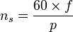
Q1/Why Does an AC Motor Need a Capacitor to Start?


You will find in this PPT all important and useful information for induction motors.
I want you to summarize some benefits from the PPT at lest one.
 
This technical manual for Three-Phase Induction Motors is the first publication of a series on the topic of "Motor Management".
With these published fundamentals the user will have a growing reference
work on the performance and operational data required for design and
application. The following topics will be covered:

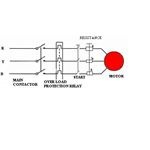
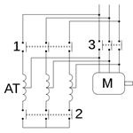
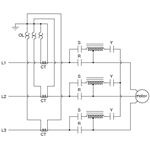
• Starting and operating motors
• Protection of motors and drives
• Selection and operation of controls
• Communications

Electric motors can be found in almost every production process today.
Getting the most out of your application is becoming more and more 
important in order to ensure cost-effective operations. "Motor Management"
from Rockwell Automation will help you:

• to optimize the use of your systems
• to reduce maintenance costs
• to increase dependability

We are pleased that our publications may help you find economical and
efficient solutions for your applications.

Content:
Design
Duty Types
Selection
Dimensioning
Copyright © 1996 by Sprecher+Schuh AG Rockwell Automation, Aarau. 
All information supplied is accurate to the best of our knowledge and without legal liability.
 
Synchronous speed
The synchronous speed of an AC motor is the rotation rate of the rotating magnetic field created by the stator. It is always an integer fraction of the supply frequency. The synchronous speed ns in revolutions per minute (RPM) is given by:

where f is the frequency of the AC supply current in Hz and p is the number of magnetic pole pairs per phase. When using total number of poles, use 120 as constant instead of 60.;For example, a small 3-phase motor typically has six magnetic poles organized as three opposing pairs 120° apart, each powered by one phase of the supply current. So there is one pair of poles per phase, which means p = 1, and for a line frequency of 50 Hz the synchronous speed is 3000 RPM.
Slip
Typical torque curve as a function of slip (slip is represented by g here, which is proportional to s in the formula at left).
Slip s is the rotation rate of the magnetic field, relative to the rotor, divided by the absolute rotation rate of the stator magnetic field

where  is the rotor rotation speed in rpm. Slip is zero at synchronous speed and 1 (100%) when the rotor is stationary. The slip determines the motor's torque. Since the short-circuited rotor windings have small resistance, a small slip induces a large current in the rotor and produces large torque.At full rated load, typical values of slip are 4-6% for small motors and 1.5-2% for large motors, so induction motors have good speed regulation and are considered constant-speed motors
 
    1. This starter is used with a wound rotor induction motor. It uses an external resistance/phase in the rotor circuit so that rotor will develop a high value of torque.
    2. High torque is produced at low speeds, when the external resistance is at its higher value.
    3. At start, supply power is connected to stator through a three pole contactor and, at a same time, an external rotor resistance is added.
    4. The high resistance limits staring current and allows the motor to start safely against high load.
    5. Resistors are normally of the wire-wound type, connected through brushes and slip rings to each rotor phase. They are tapped with points brought out to fixed contactors.
    6. As the motor starts, the external rotor resistance is gradually cut out of circuit ; the handle or starter is turned and moves the three contacts simultaneously from one fixed contact to the next.
    7. The three moving contacts are interconnected to form a start point for the resistors.
    8. To ensure that the motor cannot be started until all rotor resistance is in circuit, an interlock is fitted which prevents the contactors from being closed until this condition is fulfilled.

 
  1. Operated by a two position switch i.e. manually / automatically using a timer to change over from start to run position.
  2. In starting position supply is connected to stator windings through an auto-transformer which reduces applied voltage to 50, 60, and 70% of normal value depending on tapping used.
  3. Reduced voltage reduces current in motor windings with 50% tapping used motor current is halved and supply current will be half of the motor current. Thus starting current taken from supply will only be 25% of the taken by DOL starter.
  4. For an induction motor, torque T is developed by V2, thus on 50% tapping, torque at starting is only (0.5V)2 of the obtained by DOL starting. Hence 25% torque is produced.
  5. Starters used in lager industries, it is larger in size and expensive.
  6. Switching from start to run positions causing transient current, which can be greater in value than those obtained by DOL starting.
 
A three phase motor will give three times the power output when the stator windings are connected in delta than if connected in star, but will take 1/3 of the current from the supply when connected in star than when connected in delta. The starting torque developed in star is ½ that when starting in delta.

  1. A two-position switch (manual or automatic) is provided through a timing relay.
  2. Starting in star reduces the starting current.
  3. When the motor has accelerated up to speed and the current is reduced to its normal value, the starter is moved to run position with the windings now connected in delta.
  4. More complicated than the DOL starter, a motor with a star-delta starter may not produce sufficient torque to start against full load, so output is reduced in the start position. The motors are thus normally started under a light load condition.
  5. Switching causes a transient current which may have peak values in excess of those with DOL.
 
  1. It is simple and cheap starter for a 3-phase induction motor.
  2. The contacts close against spring action.
  3. This method is normally limited to smaller cage induction motors, because starting current can be as high as eight times the full load current of the motor. Use of a double –cage rotor requires lower staring current( approximately four times) and use of quick acting A.V.R enables motors of 75 Kw and above to be started direct on line.
  4. An isolator is required to isolate the starter from the supply for maintenance.
  5. Protection must be provided for the motor. Some of the safety protections are over-current protection, under-voltage protection, short circuit protection, etc. Control circuit voltage is sometimes stepped down through an autotransformer.
 
  1. Direct –On– line (DOL) starters for less than 10 Kw motors.
  2. Star–Delta starters for large motors. The stator winding is initially connected in a star configuration and later on changed over to a Delta connection, when the motor reaches rated speed.
  3. Auto transformer.
 
The 3-phase induction motors are of three types depending upon the type of rotor they employ namely

(i) Squirrel cage rotor

(ii) Wound rotor or slip-ring

(iii) Double squirrel cage rotor induction motors. The principle of operation is same for all types of induction motors.

    Author

    This blog include some info,video,books,PPT...all about induction motor.

     I hope you get benefits from our blog.

    Posts by: Abdullah 
    Al-ghamdi and Yazeed Alamri.

    Archives

    December 2012
    November 2012

    Categories

    All