|
Objective of the lecture:
This lecture will provide information on the following aspects: a. To study the construction of 3 type of motor. b. To study the different starting methods of of 3 type of motor. c. To study how to reverse the direction of rotation in 3 type of motor. Induction Motors Induction motors are the most commonly used prime mover for various equipments in industrial applications. In induction motors, the induced magnetic field of the stator winding induces a current in the rotor. |
Induction Motor Lesson in PPT
|
This induced rotor current
produces a second magnetic field, which tries to oppose the
stator magnetic field, and this causes the rotor to rotate.
The 3-phase squirrel cage motor is the workhorse of
industry; it is rugged and reliable, and is by far the most
common motor type used in industry.
These motors drive
pumps, blowers and fans, compressors, conveyers and production lines. The 3-phase induction
motor has three windings each connected to a separate phase of the power supply.
Theory Construction:
The induction motor essentially consists of two parts:
· Stator.
· Rotor.
The supply is connected to the stator and the rotor received power by induction
caused by the stator rotating flux, hence the motor obtains its name -induction
motor.
The stator consists of a cylindrical laminated & slotted core placed in a frame of
rolled or cast steel. The frame provides mechanical protection and carries the
terminal box and the end covers with bearings.
In the slots of a 3-phase winding
of insulated copper wire is distributed which can be wound for 2,4,6 etc. poles.
The rotor consists of a laminated and slotted core tightly pressed on the shaft.
There are two general types of rotors:
· The squirrel-cage rotor,
· The wound (or slip ring) rotor.
In the squirrel-cage rotor, the rotor winding consists of single copper or
aluminium bars placed in the slots and short-circuited by end-rings on both sides
of the rotor.
In the wound rotor, an insulated 3-phasewinding similar to the stator winding
and for the same number of poles is placed in the rotor slots.
The ends of the star-connected rotor winding are brought to three slip rings on the shaft so theta
connection can be made to it for starting or speed control.
Methods of Starting:
The most usual methods of starting 3-phase induction motors are:
1. For slip-ring motors- rotor resistance starting2. For squirrel-cage motors
- direct-on -line starting
- star-delta starting
- Auto transformer starting.
There are two important factors to be considered in starting of induction motors:
¨ the starting current drawn from the supply, and
¨ The starting torque.
The starting current should be kept low to avoid overheating of motor and
excessive voltage drops in the supply network. The starting torque must be
about 50 to 100% more than the expected load torque t ensure that the motor
runs up in a reasonably short time.
a. Rotor resistance starting
By adding eternal resistance to the rotor circuit any starting torque up to the
maximum torque can be achieved; and by gradually cutting out the resistance a
high torque can be maintained throughout the starting period.
The added
resistance also reduces the starting current, so that a starting torque in the range
of 2 to 2.5 times the full load torque can be obtained at a starting current of 1 to
1.5 times the full load current.
b. Direct-on-line starting
This is the most simple and inexpensive method of starting a squirrel cage
induction motor. The motor is switched on directly to full supply voltage. The
initial starting current is large, normally about 5 to 7 times the rated current but
the starting torque is likely to be 0.75 to 2 times the full load torque.
To avoid
excessive supply voltage drops because of large starting currents the method is
restricted to small motors only.
To decrease the starting current cage motors of medium and larger sizes are
started at a reduced supply voltage. The reduced supply voltage starting is
applied in the next two methods.
c. Star-Delta starting
This is applicable to motors designed for delta connection in normal running
conditions. Both ends of each phase of the stator winding are brought out and
connected to a 3-phase change -over switch.
For starting, the stator windings are
connected in star and when the machine is running the switch is thrown quickly
to the running position, thus connecting the motor in delta for normal operation.The phase voltages & the phase currents of the motor in star connection are
reduced to 1/Ö3 of the direct -on -line values in delta.
The line current is 1/3 of
the value in delta.
A disadvantage of this method is that the starting torque (which is proportional
to the square of the applied voltage) is also reduced to 1/3 of its delta value.
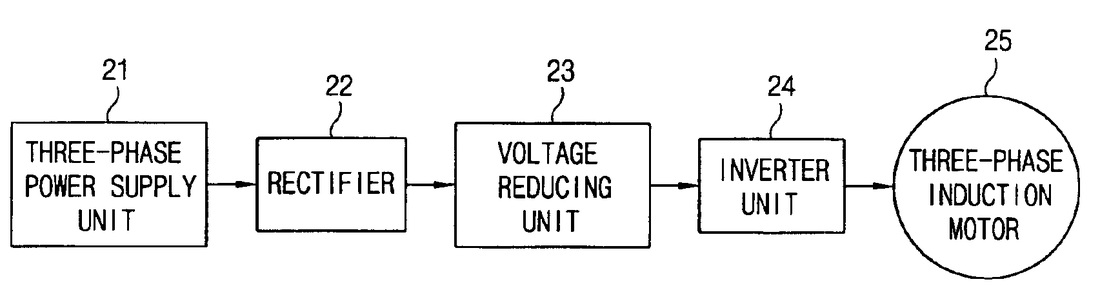
d. Auto-transformer starting
This method also reduces the initial voltage applied to the motor and therefore
the starting current and torque. The motor, which can be connected permanently
in delta or in star, is switched first on reduced voltage from a 3-phase tapped
auto -transformer and when it has accelerated sufficiently, it is switched to the
running (full voltage) position.
The principle is similar to star/delta starting and
has similar limitations. The advantage of the method is that the current and
torque can be adjusted to the required value, by taking the correct tapping on the
auto transformer. This method is more expensive because of the additional
auto transformer.
1. For slip-ring motors- rotor resistance starting2. For squirrel-cage motors
- direct-on -line starting
- star-delta starting
- Auto transformer starting.
There are two important factors to be considered in starting of induction motors:
¨ the starting current drawn from the supply, and
¨ The starting torque.
The starting current should be kept low to avoid overheating of motor and
excessive voltage drops in the supply network. The starting torque must be
about 50 to 100% more than the expected load torque t ensure that the motor
runs up in a reasonably short time.
a. Rotor resistance starting
By adding eternal resistance to the rotor circuit any starting torque up to the
maximum torque can be achieved; and by gradually cutting out the resistance a
high torque can be maintained throughout the starting period.
The added
resistance also reduces the starting current, so that a starting torque in the range
of 2 to 2.5 times the full load torque can be obtained at a starting current of 1 to
1.5 times the full load current.
b. Direct-on-line starting
This is the most simple and inexpensive method of starting a squirrel cage
induction motor. The motor is switched on directly to full supply voltage. The
initial starting current is large, normally about 5 to 7 times the rated current but
the starting torque is likely to be 0.75 to 2 times the full load torque.
To avoid
excessive supply voltage drops because of large starting currents the method is
restricted to small motors only.
To decrease the starting current cage motors of medium and larger sizes are
started at a reduced supply voltage. The reduced supply voltage starting is
applied in the next two methods.
c. Star-Delta starting
This is applicable to motors designed for delta connection in normal running
conditions. Both ends of each phase of the stator winding are brought out and
connected to a 3-phase change -over switch.
For starting, the stator windings are
connected in star and when the machine is running the switch is thrown quickly
to the running position, thus connecting the motor in delta for normal operation.The phase voltages & the phase currents of the motor in star connection are
reduced to 1/Ö3 of the direct -on -line values in delta.
The line current is 1/3 of
the value in delta.
A disadvantage of this method is that the starting torque (which is proportional
to the square of the applied voltage) is also reduced to 1/3 of its delta value.
d. Auto-transformer starting
This method also reduces the initial voltage applied to the motor and therefore
the starting current and torque. The motor, which can be connected permanently
in delta or in star, is switched first on reduced voltage from a 3-phase tapped
auto -transformer and when it has accelerated sufficiently, it is switched to the
running (full voltage) position.
The principle is similar to star/delta starting and
has similar limitations. The advantage of the method is that the current and
torque can be adjusted to the required value, by taking the correct tapping on the
auto transformer. This method is more expensive because of the additional
auto transformer.
Reversing:
The direction that a three phase induction motor rotates is determined by the direction of the rotation of the stator field.
The direction is therefore determined by the rotation of the three phases applied to the motor. To reverse the direction of rotation of an induction motor, interchange two phases connected to the motor.
Supply motor
L1 U1
L2 V1
L3 W1
To reverse, change to:
Supply motor
L2 U1
L1 V1
L3 W1
The direction is therefore determined by the rotation of the three phases applied to the motor. To reverse the direction of rotation of an induction motor, interchange two phases connected to the motor.
Supply motor
L1 U1
L2 V1
L3 W1
To reverse, change to:
Supply motor
L2 U1
L1 V1
L3 W1
For more information, go to the next page to learn from our podcast.
