1. This starter is used with a wound rotor induction motor. It uses an external resistance/phase in the rotor circuit so that rotor will develop a high value of torque.
    2. High torque is produced at low speeds, when the external resistance is at its higher value.
    3. At start, supply power is connected to stator through a three pole contactor and, at a same time, an external rotor resistance is added.
    4. The high resistance limits staring current and allows the motor to start safely against high load.
    5. Resistors are normally of the wire-wound type, connected through brushes and slip rings to each rotor phase. They are tapped with points brought out to fixed contactors.
    6. As the motor starts, the external rotor resistance is gradually cut out of circuit ; the handle or starter is turned and moves the three contacts simultaneously from one fixed contact to the next.
    7. The three moving contacts are interconnected to form a start point for the resistors.
    8. To ensure that the motor cannot be started until all rotor resistance is in circuit, an interlock is fitted which prevents the contactors from being closed until this condition is fulfilled.

 
  1. Operated by a two position switch i.e. manually / automatically using a timer to change over from start to run position.
  2. In starting position supply is connected to stator windings through an auto-transformer which reduces applied voltage to 50, 60, and 70% of normal value depending on tapping used.
  3. Reduced voltage reduces current in motor windings with 50% tapping used motor current is halved and supply current will be half of the motor current. Thus starting current taken from supply will only be 25% of the taken by DOL starter.
  4. For an induction motor, torque T is developed by V2, thus on 50% tapping, torque at starting is only (0.5V)2 of the obtained by DOL starting. Hence 25% torque is produced.
  5. Starters used in lager industries, it is larger in size and expensive.
  6. Switching from start to run positions causing transient current, which can be greater in value than those obtained by DOL starting.
 
A three phase motor will give three times the power output when the stator windings are connected in delta than if connected in star, but will take 1/3 of the current from the supply when connected in star than when connected in delta. The starting torque developed in star is ½ that when starting in delta.

  1. A two-position switch (manual or automatic) is provided through a timing relay.
  2. Starting in star reduces the starting current.
  3. When the motor has accelerated up to speed and the current is reduced to its normal value, the starter is moved to run position with the windings now connected in delta.
  4. More complicated than the DOL starter, a motor with a star-delta starter may not produce sufficient torque to start against full load, so output is reduced in the start position. The motors are thus normally started under a light load condition.
  5. Switching causes a transient current which may have peak values in excess of those with DOL.
 
  1. It is simple and cheap starter for a 3-phase induction motor.
  2. The contacts close against spring action.
  3. This method is normally limited to smaller cage induction motors, because starting current can be as high as eight times the full load current of the motor. Use of a double –cage rotor requires lower staring current( approximately four times) and use of quick acting A.V.R enables motors of 75 Kw and above to be started direct on line.
  4. An isolator is required to isolate the starter from the supply for maintenance.
  5. Protection must be provided for the motor. Some of the safety protections are over-current protection, under-voltage protection, short circuit protection, etc. Control circuit voltage is sometimes stepped down through an autotransformer.
 
  1. Direct –On– line (DOL) starters for less than 10 Kw motors.
  2. Star–Delta starters for large motors. The stator winding is initially connected in a star configuration and later on changed over to a Delta connection, when the motor reaches rated speed.
  3. Auto transformer.
 
The 3-phase induction motors are of three types depending upon the type of rotor they employ namely

(i) Squirrel cage rotor

(ii) Wound rotor or slip-ring

(iii) Double squirrel cage rotor induction motors. The principle of operation is same for all types of induction motors.

 
This is the basic principle of how induction motors work Video.
There is a lot more to say about motors, as starter winding with steady capacitor, multiple pole windings, three phases motor, etc etc, but the basic theory is this one !
Did you enjoy with this video ?
Did you learn something with this video?
Ok! I will ask you question about what you learnt.
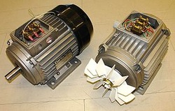
what induction motor consist of ?
 
Picture
The idea of a rotating magnetic field was developed by François Arago in 1824, and first implemented by Walter Baily

Based on this, practical alternating current induction motors seem to have been independently invented by                          Nikola Tesla and Galileo Ferraris.

 Ferraris demonstrated a working model of his motor in 1885 and Tesla built his working model in 1887 and demonstrated it at the American Institute of Electrical Engineers in 1888(although Tesla claimed that he conceived the rotating magnetic field in 1882). 

In 1888, Ferraris published his research to the Royal Academy of Sciences in Turin, where he detailed the foundations of motor operation; Tesla, in the same year, was granted a United States patent for his own motor.

The modern system of a three-phase transformer and induction motor with a cage was invented by Mikhail Dolivo-Dobrovolsky in 1889/1890.

 
In this blog, my plan is to post what I’ve found useful,include some info,video,books,PPT...all about induction motor.

I hope you get benefits from our blog.

Posts by: Abdullah Al-ghamdi and Yazeed Alamri.

    Author

    This blog include some info,video,books,PPT...all about induction motor.

     I hope you get benefits from our blog.

    Posts by: Abdullah 
    Al-ghamdi and Yazeed Alamri.

    Archives

    December 2012
    November 2012

    Categories

    All